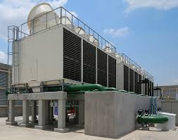
Cooling Tower Basic Calculations
February 28, 2017 0 Comments

The recirculation rate and the temperature drop across the cooling tower are the two pieces of data needed to calculate the amount of water lost from the open recirculating cooling system (due to evaporation).
Following items will be discussed and calculated in this article :
- Evaporation
- Temperature Drop
- Recirculation Rate
- Concentration Ratio or Cycles of Concentration
- Make Up Water
- Holding Capacity or System Volume
- Blowdown Rate
Evaporation:
- Evaporation losses will vary depending upon temperature and humidity, but a general rule is that for every 100 F. (60 C.) temperature drop across the tower, approximately 0.85% of the recirculation rate will be evaporated.
- Evaporation (Estimation: See Value Added Troubleshooting Guide - Cooling Section for precise method )
- E = ∆T × R × 0.00085 when T measured in Fahrenheit
- E = ∆T × R × 0.00153 when T measured in Centigrade
- Where: R = Recirculation Rate, gpm (m3/hr)
- Units will be equivalent to the R value. Typically gpm or m3/hr.
This figure can be used for estimating purposes, but should not be used when more exact information is required (e.g., in a proposal, problem solving, etc.). Details for calculating evaporation rate based upon temperature and humidity conditions are provided in the PAC-3 section of the Value Added Troubleshooting Guide.
Temperature Drop :
The temperature drop ( ∆T ) for a cooling tower can be measured by taking the temperature of the tower return water (TR) and subtracting the temperature of the basin supply water (TS). This difference can be used to calculate the approximate amount of evaporation that has occurred in the cooling tower:
∆T = TR − TS Recirculation Rate
To maintain a flow of water through the heat transfer equipment, water must be pumped or recirculated. The recirculation rate can be determined from information on pump performance, tower hydraulics, etc. A detailed description of how to determine recirculating rate is given in the PAC-3 section of the Value Added Troubleshooting Guide .
It can be grossly misleading to simply use the pump name plate data to determine recirculating rate. Many times throttling valves, pipe restrictions, and head pressure restrictions interfere and can produce deviations as great as 50-75% from the name plate values.
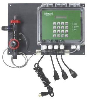
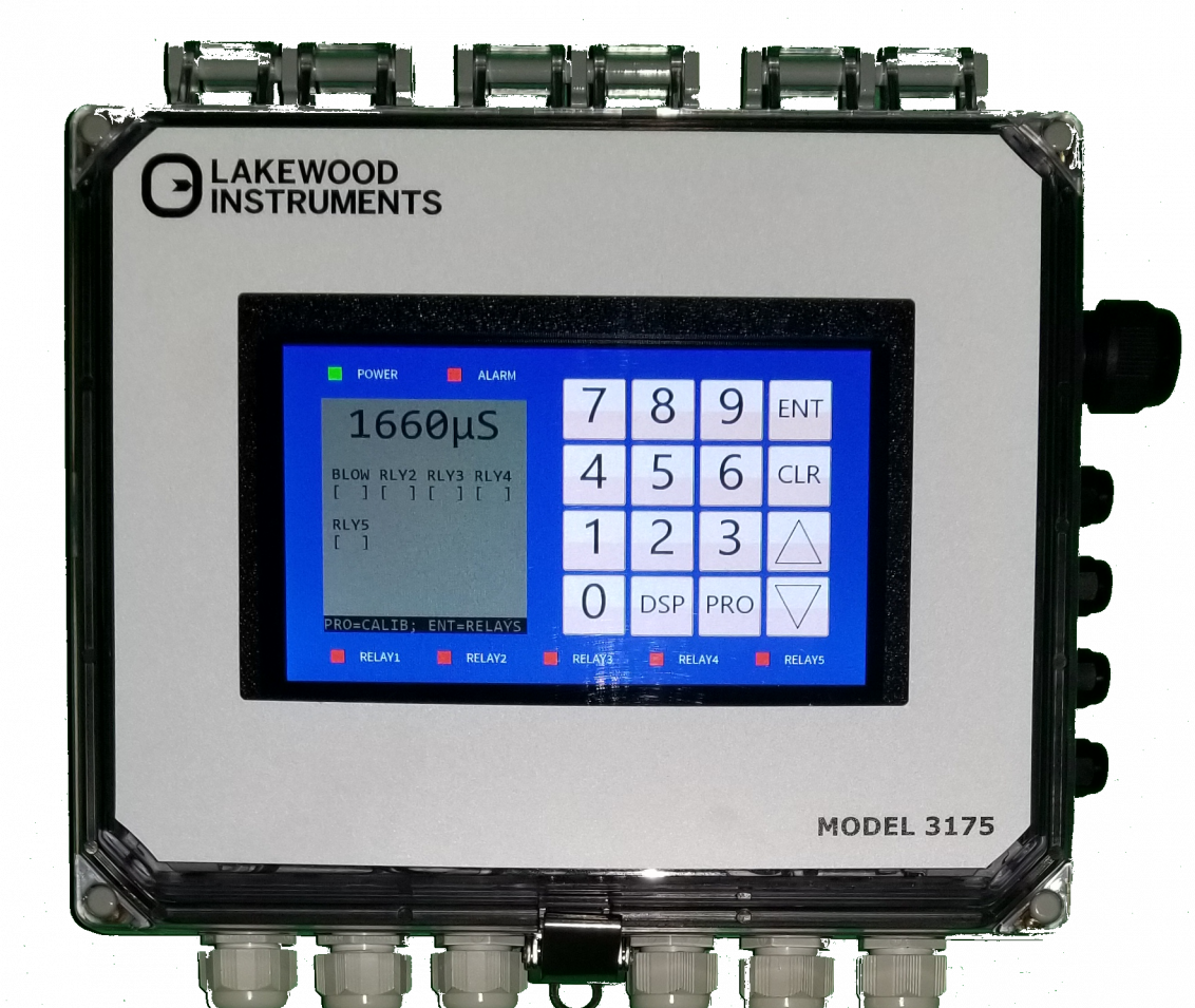
Check out our cooling tower conductivity controller, just click here!
Concentration Ratio or Cycles of Concentration
The concentration ratio of an ion carried in a recirculating system is merely the concentration of that ion in the recirculating water divided by the concentration of the ion in the makeup water. Concentration ratio is also referred to as the cycles of concentration.
C R = Specific Ion Concentration in the Recirculation Water Specific Ion
Concentration in the Make Up Water
Theoretically, evaporation from a cooling tower is pure water. All of the dissolved ions are left behind to concentrate in the system. If the only system water loss was through evaporation, the dissolved ions in the recirculating water would continue to concentrate (from the ions left after evaporation) until the solubility of each ion in the water was exceeded and massive scale/deposition resulted. Most systems cannot tolerate any scale; therefore, the level or concentration of critical scaling-prone ions in the water is usually controlled by a combination of bleeding off a certain portion of the recirculation water and adding anti-scaling compounds. The rate at which water is bled from a system (in gpm; m3/hr) compared with the amount of fresh water being introduced in the system (in gpm; m3/hr) will also determine the concentration ratio.
CR= MU / BD
To check the concentration ratio in a system, select and monitor a soluble ion (such as silica or magnesium) that is present in sufficient quantity, stable, and easily tested. Compare its concentration in the makeup water to its concentration in the recirculating water by dividing the tower content by the makeup content.
Repeating this same testing for scaling species (e.g., calcium) will provide an indication if scaling is occurring or if the system is in chemical balance. If the cycles of calcium concentration are consistently lower than the cycles of magnesium concentration, for example, the calcium can be assumed to be precipitating in the system. (There may also be scale forming in the heat transfer equipment, thereby impeding production.) Entry of ions from sources other than the makeup water can invalidate any ratio being developed. These sources include chlorination, chemical additives, process leaks, acid additions, and airborne gases.
Make Up Water :
Water that must be added to replace water lost from the recirculating system by evaporation and bleed-off (or blowdown) is called makeup water (MU). The amount of water entering the system must be equal to the amount leaving the system.
MU = E + BD
Where:
MU = Makeup Rate, gpm (m3/hr)
E = Evaporation Rate, gpm (m3/hr)
BD = Blowdown Rate. gpm (m3/hr) includes drift, leakage, filter wastage and export
If the temperature drop across the tower and the recirculation rates are known, the amounts of water loss through evaporation can be calculated. If the concentration ratio is also known then the makeup water requirements can be calculated as follows.
MU = E × CR CR −1
The expression was developed from the following fundamental cooling tower water balance relationships.
MU = E + BD
CR = MU/BD
Substituting BD = MU/CR in the first equation. MU = E + MU/CR
(MU)(CR) = (E)(CR) + MU
(MU)(CR) - MU = (E)(CR)
MU = E × CR / (CR −1)
The blowdown (bleed-off) rate is generally defined as the water lost from the system for all reasons except evaporation. In very tight (low water loss) open recirculating systems, the two primary areas for system water loss are evaporation and water blowdown. In practice, however, a lot of water may also be lost through system water leaks, by water combining with the product or process, or by tower drift. Indsutry standard is the installation of a cooling blowdown controller, to adjust the amount of blowdown automatically. For calculation purposes, all of these water losses, except for evaporation, are generally considered together and called tower water blowdown. The blowdown rate is normally measured in gallons pen minute (m3/hr).
System blowdown (BD) rate can be calculated from the following expression:
BD= E x( CR −1)
Where: BD = blowdown rate, gpm (m3/hr)
E = tower evaporation rate, gpm (m3/hr)
CR = concentration ratio or cycles
This expression was derived from the following cooling tower water balance relationship: MU = BD + E
Substituting MU = (CR)(BD) in MU = BD + E : (CR)(BD) = BD + E
(CR)(BD) - BD = E
(BD)(CR-1) = E
BD= E (CR −1)
Check out the best blowdown control valve in the market, just click here!
Non-Blowdown Water Losses Included in Blowdown [ Drift, Leaks, Filter Wastage, Export ]
If cooling system is operated under ideal conditions all water removed from the system would be due to evaporation or blowdown. Unfortunately the ideal cooling system only exist in concept and in operating systems we find other water losses that need to be understood and factored into the overall cooling system materials balance equation.
The blowdown is normally controlled utilizing automatic systems and valves.
Drift - Tiny droplets of water that become entrained in the airstream and carried out of the unit in the leaving airstream. Unlike evaporation drift is a droplet of water and contains solids and bacteria. Drift is the primary mechanism for transmission of pathogens from a cooling system to a host. Drift is usually estimated based on a percentage of recirculation. Estimates vary from 0.002 to 0.01% of recirculation.
Splash fill towers tend to have higher drift rates then film fill towers. Drift eliminator design, unit maintenance and air flow also have an influence on the amount of drift that is released from a cooling system.
Leaks - Uncontrolled water lost from a system. Leaks should be identified, quantified and corrected where possible. Leak identification and management is a valuable service to any client operating a cooling system. Possible sources: pump seals, valves that do not seal, overflow, tower containment or splash out, exchanger failures . . .
Filter / Separator Wastage - Water wasted from a system due to separator flush or filter back wash.
Export - Water intentionally removed from the system and used in another system.
Holding Capacity or System Volume :
The holding capacity of a system is the amount of water in the system expressed in gallons (cubic meters). Normally most of the capacity of a system is contained in the cooling tower basin; the exact amount, however, can be determined only by conducting a TRASAR diagnosis or an ion concentration study. This technique is described in detail in the Value Added Troubleshooting Guide, PAC-3 . Assumptions about holding capacities can be dangerous and may lead to incorrect dosages for biocides, including biological control programs that are ineffective or too costly.
Holding Time Index or Half-Life
The holding time index (HTI) is a calculated figure that indicates the time required to reduce the chemical or makeup water added to a system to 50% of its original concentration. It is essentially the half-life of a chemical added to the system. The basic method of calculating the holding time index is as follows:
HTI = 0.693 ×HC BD
Expressed in the time units used for blowdown BD. Usually reported in hours.
Where: BD = Blowdown Rate. gpm (m3/hr) includes leakage
HC = Holding Capacity or Volume, gal (m3)
The holding time index is important in choosing a chemical treatment program. Very long holding time indexes may preclude the use of certain chemicals, such as polyphosphates, because of excessive reversion of the polyphosphate species to orthophosphate and subsequent precipitation as tricalcium phosphate (a compound that has a very low solubility in water). A short holding time index may limit the use of some chemicals because of the higher amount of chemical required to maintain the necessary treatment levels (and the accompanying increased costs). Further, not all chemical inhibitors will prevent scale, corrosion, and fouling for the same length of time. Therefore, the particular chemical program chosen and the level at which the chemicals are applied are influenced by the holding time index.
Finally, the holding time index is used to determine the required amount of some biocides to achieve proper control of microorganisms. This is particularly true when slug feeding slower-acting biocides. Short holding time indexes may not allow enough time to maintain critical biocide concentration for kill and can result in developing resistance. We can manage holding time index to some degree by pre- blowing down prior to biocide dosing to increase the holding time.
Need a metering pump to feed chemicals in your cooling tower? Just click here!
TIME PER CYCLE :
The time per cycle is defined as the time it takes all the water in a system to make one trip around the recirculating loop (from the discharge side of the recirculation pump back to the suction side of the pump).
Time per Cycle = HCxR
Recirculation rate R.
Expressed in the time units used for
Where: BD = Blowdown Rate. gpm (m3/hr) includes drift and leakage
CR = Concentration Ratio
E = Evaporation Rate, gpm (m3/hr)
HC = Holding Capacity or Volume, gal (m3) HTI = Holding Time Index
MU = Makeup Rate, gpm (m3/hr)
R = Recirculation Rate, gpm (m3/hr)
You maybe interested:
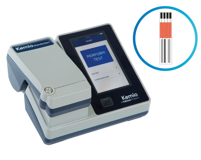
EASIEST WAY OF MEASURING FREE AND TOTAL CHLORINE IN WATER!
NON EXPERT COOLING CONTROLLER SELECTION TUTORIAL
HERE IS WHY YOU NEED TO REPLACE YOUR SOLENOID VALVE
Also in Blog

Advanced Cooling Tower Management: Enhancing Efficiency with Lakewood Model 140
February 28, 2024 0 Comments

Optimizing Cooling Tower Performance: Understanding Efficiency, Maintenance, and Water Quality Management
February 28, 2024 0 Comments

Revolutionizing Water Analysis: Everything You Need to Know About the Kemio KEM10DIS
April 19, 2023 0 Comments


