What is a heat exchanger?

Heat exchangers are devices designed to transfer heat between two or more fluids—i.e., liquids, vapors, or gases—of different temperatures. Depending on the type of heat exchanger employed, the heat transferring process can be gas-to-gas, liquid-to-gas, or liquid-to-liquid and occur through a solid separator, which prevents mixing of the fluids, or direct fluid contact. Other design characteristics, including construction materials and components, heat transfer mechanisms, and flow configurations, also help to classify and categorize the types of heat exchangers available. Finding application across a wide range of industries, a diverse selection of these heat exchanging devices are designed and manufactured for use in both heating and cooling processes.
This article focuses on heat exchangers, exploring the various designs and types available and explaining their respective functions and mechanisms. Additionally, this article outlines the selection considerations and common applications for each type of heat exchanging device.
Heat Exchanger Thermodynamics
The design of a heat exchanger is an exercise in thermodynamics, which is the science that deals with heat energy flow, temperature, and the relationships to other forms of energy. To understand heat exchanger thermodynamics, a good starting point is to learn about the three ways in which heat can be transferred – conduction, convection, and radiation. In the sections below, a review of each of these heat transfer modes is presented.
Conduction
Conduction is the passing of thermal energy between materials that are in contact with one another. Temperature is a measure of the average kinetic energy of molecules in a material – warmer objects (that are at a higher temperature) are exhibiting more molecular motion. When a warmer object is brought in contact with a cooler object (one that is at a lower temperature), there is a thermal energy transfer between the two materials, with the cooler object becoming more energized and the warmer object becoming less energized. This process will continue until thermal equilibrium has been achieved.
The rate at which heat energy is transferred in a material by thermal conduction is given by the following expression:

In this expression, Q represents the amount of heat transferred through the material in time t, ΔT is the temperature difference between one side of the material and the other (the thermal gradient), A is the cross-sectional area of the material, and d is the thickness of the material. The constant k is known as the thermal conductivity of the material and is a function of the material’s intrinsic properties and its structure. Air and other gases generally have low thermal conductivities, while non-metallic solids exhibit higher values and metallic solids generally showing the highest values.
Convection
Convection is the transfer of thermal energy from a surface by way of the motion of a fluid such as air or water that has been heated. Most fluids expand when heated and therefore will become less dense and rise relative to other parts of the fluid that are cooler. So, when the air in a room is heated, it rises to the ceiling because it is warmer and less dense, and transfers heat energy as it collides with the cooler air in the room, then becoming denser and falling again towards the floor. This process creates a natural or free convection current. Convection can also occur through what is termed forced or assisted convection, such as when heated water is pumped through a pipe such as in a hydronic heating system.
For free convection, the rate of transfer of heat is expressed by Newton’s law of cooling:

Where Q-dot is the rate of transfer of heat, hc is the convective heat transfer coefficient, A is the surface area over which the convection process is occurring, and ΔT is the temperature differential between the surface and the fluid. The convective heat transfer coefficient hc is a function of the properties of the fluid, similar to the thermal conductivity of the material mentioned earlier regarding conduction.
Radiation
Thermal radiation is a mechanism of heat energy transfer that involves the emission of electromagnetic waves from a heated surface or object. Unlike conduction and convection, thermal radiation does not require an intermediate medium to carry the wave energy. All objects whose temperature is above absolute zero (-273.15oC) emit thermal radiation in a typically broad spectral range.
The net rate of radiation heat loss can be expressed using the Stefan-Boltzmann Law as follows:

where Q is the heat transfer per unit time, Th is the temperature of the hot object (in absolute units, oK), Tc is the temperature of the colder surroundings (also in absolute units, oK), σ is the Stefan-Boltzmann constant (whose value is 5.6703 x 10⁻⁸ W/m2K4). The term represented by ε is the emissivity coefficient of the material and can have a value anywhere between 0 to 1, depending on the characteristics of the material and its ability to reflect, absorb, or transmit radiation. It is also a function of the temperature of the material.
Basic Principles Underlying Heat Exchangers
Regardless of the type and design, all heat exchangers operate under the same fundamental principles—namely the Zeroth, First, and Second Laws of Thermodynamics—which describe and dictate the transference or “exchange” of heat from one fluid to another.
- The Zeroth Law of Thermodynamics states that thermodynamic systems that are in thermal equilibrium have the same temperature. Furthermore, if two systems are each in thermal equilibrium with a third system, then the two former systems must be in equilibrium with each other; thus, all three systems are of the same temperature. This law, preceding the three other Laws of Thermodynamics in order but not in development, not only expresses thermal equilibrium as a transitive property but also defines the concept of temperature and establishes it as a measurable property of thermodynamic systems.
- The First Law of Thermodynamics builds upon the Zeroth Law, establishing internal energy (U) as another property of thermodynamic systems and indicating the influence of heat and work on a system’s internal energy and the surrounding environment’s energy. Additionally, the first law—also referred to as the Law of Conversation of Energy—essentially states that energy cannot be created or destroyed, only transferred to another thermodynamic system or converted to another form (e.g., heat or work).
For example, if heat flows into the system from its surroundings, there is a corresponding increase in the internal energy of the system and a decrease in the energy of the surrounding environment. This principle can be illustrated by the following equation, where ΔUsystem represents the internal energy of the system, and ΔUenvironment represents the internal energy of the surrounding environment:

- The Second Law of Thermodynamics establishes entropy (S) as an additional property of thermodynamic systems and describes the natural and invariable tendency of the universe, and any other closed thermodynamic system, to increase in entropy over time. This principle can be illustrated by the following equation where ΔS represents the change in entropy, ΔQ represents the change in the heat added to the system, and T represents the absolute temperature:

It is also used to explain the tendency of two isolated systems—when allowed to interact and free from all other influences—to move towards thermodynamic equilibrium. As established by the Second Law, entropy can only increase, never decrease; consequently, each system, as the entropy increases, invariably moves towards the highest value achievable for said system. At this value, the system reaches a state of equilibrium where entropy can no longer increase (as it is at the maximum), nor decrease, as that action would violate the Second Law. Therefore, the only system changes possible are the ones in which entropy does not experience change (i.e., the ratio of the heat added or subtracted to the system to the absolute temperature remains constant).
Altogether, these principles dictate the underlying mechanisms and operations of heat exchangers; the Zeroth law establishes temperature as a measurable property of thermodynamic systems, the First Law describes the inverse relationship between a system’s internal energy (and its converted forms) and that of its surrounding environment, and the Second Law expresses the tendency for two interacting systems to move towards thermal equilibrium. Thus, heat exchangers function by allowing a fluid of higher temperature (F1) to interact—either directly or indirectly—with a fluid of a lower temperature (F2), which enables heat to transfer from F1 to F2 to move towards equilibrium. This transfer of heat results in a decrease in temperature for F1 and an increase in temperature for F2. Depending on whether the application is aimed towards heating or cooling a fluid, this process (and devices that employ it) can be used to direct heat towards or away from a system, respectively.
Heat Exchanger Design Characteristics
As outlined above, all heat exchangers operate under the same basic principles. However, these devices can be classified and categorized in several different ways based on their design characteristics. The main characteristics by which heat exchangers can be categorized include:
- Flow configuration
- Construction method
- Heat transfer mechanism
Flow Configuration
The flow configuration, also referred to as the flow arrangement, of a heat exchanger refers to the direction of movement of the fluids within the heat exchanger in relation to each other. There are four principal flow configurations employed by heat exchangers:
- Cocurrent flow
- Countercurrent flow
- Crossflow
- Hybrid flow
Cocurrent Flow
Cocurrent flow heat exchangers, also referred to as parallel flow heat exchangers, are heat exchanging devices in which the fluids move parallel to and in the same direction as each other. Although this configuration typically results in lower efficiencies than a counter flow arrangement, it also allows for the greatest thermal uniformity across the walls of the heat exchanger.
Countercurrent Flow
Countercurrent flow heat exchangers, also known as counter flow heat exchangers, are designed such that the fluids move antiparallel (i.e., parallel but in opposite directions) to each other within the heat exchanger. The most commonly employed of the flow configurations, a counter flow arrangement typically exhibits the highest efficiencies as it allows for the greatest amount of heat transference between fluids and, consequently, the greatest change in temperature.
Crossflow
In crossflow heat exchangers, fluids flow perpendicularly to one another. The efficiencies of heat exchangers which employ this flow configuration fall between that of countercurrent and cocurrent heat exchangers.
Hybrid Flow
Hybrid flow heat exchangers exhibit some combination of the characteristics of the previously mentioned flow configurations. For example, heat exchanger designs can employ multiple flow passes and arrangements (e.g., both counter flow and crossflow arrangements) within a single heat exchanger. These types of heat exchangers are typically used to accommodate the limitations of an application, such as space, budget costs, or temperature and pressure requirements.
Figure 1, below, illustrates the various flow configurations available, including a cross/counter flow configuration, which is an example of a hybrid flow configuration.
Figure 1 – Heat Exchanger Flow Configurations

Construction Method
While in the previous section, heat exchangers were categorized based on the type of flow configuration employed, this section categorizes them based on their construction. The construction characteristics by which these devices can be classified include:
- Recuperative vs. regenerative
- Direct vs. indirect
- Static vs. dynamic
- Types of components and materials employed
Recuperative vs. Regenerative
Heat exchangers can be classified as recuperative heat exchangers and regenerative heat exchangers.
The difference between recuperative and regenerative heat exchanger systems is that in recuperative heat exchangers (commonly called recuperators), each fluid simultaneously flows through its own channel within the heat exchanger. On the other hand, regenerative heat exchangers, also referred to as capacitive heat exchangers or regenerators, alternately allow warmer and cooler fluids to flow through the same channel. Both recuperators and regenerators can be further separated into different categories of exchangers, such as direct or indirect and static or dynamic, respectively. Of the two types indicated, recuperative heat exchangers are more commonly employed throughout industry.
Direct vs. Indirect
Recuperative heat exchangers employ either direct contact or indirect contact transfer processes to exchange heat between fluids.
In direct contact heat exchangers, the fluids are not separated within the device and heat transfers from one fluid to another through direct contact. On the other hand, in indirect heat exchangers, the fluids remain separated from one another by thermally conductive components, such as tubes or plates, throughout the heat transfer process. The components first receive heat from the warmer fluid as it flows through the heat exchanger, and then transfer the heat to the cooler fluid as it flows through. Some of the devices which employ direct contact transfer processes include cooling towers and steam injectors, while devices that employ indirect contact transfer processes include tubular or plate heat exchangers.
Static vs. Dynamic
There are two main types of regenerative heat exchangers—static heat exchangers and dynamic heat exchangers. In static regenerators (also known as fixed bed regenerators), the heat exchanger material and components remains stationary as fluids flow through the device, while in dynamic regenerators the material and components move throughout the heat transfer process. Both types are at risk of cross-contamination between fluid streams, necessitating careful design considerations during manufacturing.
In one example of the static type, warmer fluid is run through one channel while cooler fluid runs through another for a fixed period of time at the end of which, through the use of quick-operating valves, flow is reversed such that the two fluids switch channels. An example of the dynamic type typically employs a rotating, thermally conductive component (e.g., a drum) through which warmer and cooler fluids continuously flow—albeit in separate, sealed-off sections. As the component rotates, any given section alternately passes through the warmer steam and cooler streams, allowing for the component to absorb heat from the warmer fluid and transfer the heat to the cooler fluid as it passes through. Figure 2, below, depicts the heat transfer process within a rotary-type regenerator with a countercurrent flow configuration.
Figure 2 – Heat Transfer in a Rotary-Type Regenerator

Heat Exchanger Components and Materials
There are several types of components which can be employed in heat exchangers, as well as a wide range of materials used to construct them. The components and materials used depend on the type of heat exchanger and its intended application.
Some of the most common components used to construct heat exchangers include shells, tubes, spiral tubes (coils), plates, fins, and adiabatic wheels. Further detail on how these components function within a heat exchanger will be provided in the next section (see Types of Heat Exchangers).
While metals are highly suitable—and commonly used—for constructing heat exchangers due to their high thermal conductivity, as in the case of copper, titanium, and stainless steel heat exchangers, other materials, such as graphite, ceramics, composites, or plastics, may offer greater advantages depending on the requirements of the heat transfer application.
Figure 3 – Heat Exchanger Classification by Construction

Notes: *The heat exchanging devices listed beneath the construction classifications are only a small sample of those available.
**The classification breakdown depicted is as reported on Thermopedia.com.
Heat Transfer Mechanism
There are two types of heat transfer mechanisms employed by heat exchangers—single-phase or two-phase heat transfer.
In single-phase heat exchangers, the fluids do not undergo any phase change throughout the heat transfer process, meaning that both the warmer and cooler fluids remain in the same state of matter at which they entered the heat exchanger. For example, in water-to-water heat transfer applications, the warmer water loses heat which is then transferred to the cooler water and neither change to a gas or solid.
On the other hand, in two-phase heat exchangers, fluids do experience a phase change during the heat transfer process. The phase change can occur in either or both of the fluids involved resulting in a change from a liquid to a gas or a gas to a liquid. Typically, devices that employ a two-phase heat transfer mechanism require more complex design considerations than ones that employ a single-phase heat transfer mechanism. Some of the types of two-phase heat exchangers available include boilers, condensers, and evaporators.
Types of Heat Exchangers
Based on the design characteristics indicated above, there are several different variants of heat exchangers available. Some of the more common variants employed throughout industry include:
- Shell and tube heat exchangers
- Double pipe heat exchangers
- Plate heat exchangers
- Condensers, evaporators, and boilers
Shell and Tube Heat Exchangers
The most common type of heat exchangers, shell and tube heat exchangers are constructed of a single tube or series of parallel tubes (i.e., tube bundle) enclosed within a sealed, cylindrical pressure vessel (i.e., shell). The design of these devices is such that one fluid flows through the smaller tube(s), and the other fluid flows around its/their outside(s) and between it/them within the sealed shell. Other design characteristics available for this type of heat exchanger include finned tubes, single- or two-phase heat transfer, countercurrent flow, cocurrent flow, or crossflow arrangements, and single, two, or multiple pass configurations.
Some of the types of shell and tube heat exchangers available include helical coil heat exchangers and double pipe heat exchangers, and some of the applications include preheating, oil cooling, and steam generation.

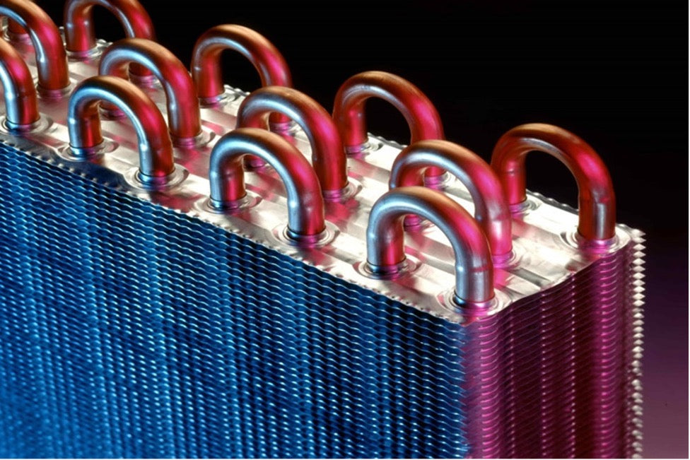
A close-up view of a heat exchanger tube bundle.
Double Pipe Heat Exchangers
A form of shell and tube heat exchanger, double pipe heat exchangers employ the simplest heat exchanger design and configuration which consists of two or more concentric, cylindrical pipes or tubes (one larger tube and one or more smaller tubes). As per the design of all shell and tube heat exchangers, one fluid flows through the smaller tube(s), and the other fluid flows around the smaller tube(s) within the larger tube.
The design requirements of double pipe heat exchangers include characteristics from the recuperative and indirect contact types mentioned previously as the fluids remain separated and flow through their own channels throughout the heat transfer process. However, there is some flexibility in the design of double pipe heat exchangers, as they can be designed with cocurrent or countercurrent flow arrangements and to be used modularly in series, parallel, or series-parallel configurations within a system. For example, Figure 4, below, depicts the transfer of heat within an isolated double pipe heat exchanger with a cocurrent flow configuration.
Figure 4 – Heat Transfer in a Double Pipe Heat Exchanger

Plate Heat Exchangers
Also referred to as plate type heat exchangers, plate heat exchangers are constructed of several thin, corrugated plates bundled together. Each pair of plates creates a channel through which one fluid can flow, and the pairs are stacked and attached—via bolting, brazing, or welding—such that a second passage is created between pairs through which the other fluid can flow.
The standard plate design is also available with some variations, such as in plate fin or pillow plate heat exchangers. Plate fin exchangers employ fins or spacers between plates and allow for multiple flow configurations and more than two fluid streams to pass through the device. Pillow plate exchangers apply pressure to the plates to increase the heat transfer efficiency across the surface of the plate. Some of the other types available include plate and frame, plate and shell, and spiral plate heat exchangers.
A close-up view of a plate type heat exchanger.

Condensers, Evaporators, and Boilers
Boilers, condensers, and evaporators are heat exchangers which employ a two-phase heat transfer mechanism. As mentioned previously, in two-phase heat exchangers one or more fluids undergo a phase change during the heat transfer process, either changing from a liquid to a gas or a gas to a liquid.
Condensers are heat exchanging devices that take heated gas or vapor and cool it to the point of condensation, changing the gas or vapor into a liquid. On the other hand, in evaporators and boilers, the heat transfer process changes the fluids from liquid form to gas or vapor form.
Other Heat Exchanger Variants
Heat exchangers are employed in a variety of applications across a wide range of industries. Consequently, there are several variants of heat exchangers available, each suitable for the requirements and specifications of a particular application. Beyond the variants mentioned above, other types available include air cooled heat exchangers, fan cooled heat exchangers, and adiabatic wheel heat exchangers.
Heat Exchanger Selection Considerations
While there are a wide variety of heat exchangers available, the suitability of each type (and its design) in transferring heat between fluids is dependent on the specifications and requirements of the application. Those factors largely determine the optimal design of the desired heat exchanger and influence the corresponding rating and sizing calculations.
Some of the factors that industry professionals should keep in mind when designing and choosing a heat exchanger include:
- The type of fluids, the fluid stream, and their properties
- The desired thermal outputs
- Size limitations
- Costs
Fluid Type, Stream, and Properties
The specific type of fluids—e.g., air, water, oil, etc.—involved and their physical, chemical, and thermal properties—e.g., phase, temperature, acidity or alkalinity, pressure and flow rate, etc.—help determine the flow configuration and construction best suited for that particular heat transfer application.
For example, if corrosive, high temperature, or high pressure fluids are involved, the heat exchanger design must be able to withstand the high stress conditions throughout the heating or cooling process. One method of fulfilling these requirements is by choosing construction materials which hold the desired properties: graphite heat exchangers exhibit high thermal conductivity and corrosion resistance, ceramic heat exchangers can handle temperatures higher than many commonly used metals’ melting points, and plastic heat exchangers offer a low-cost alternative which maintains a moderate degree of corrosion resistance and thermal conductivity.

Ceramic heat exchanger
Another method is by choosing a design suited for the fluid properties: plate heat exchangers are capable of handling low to medium pressure fluids but at higher flow rates than other types of heat exchangers, and two-phase heat exchangers are necessary when handling fluids which require a phase change throughout the heat transfer process. Other fluid and fluid stream properties that industry professionals may keep in mind when choosing a heat exchanger include fluid viscosity, fouling characteristics, particulate matter content, and presence of water-soluble compounds.
Thermal Outputs
The thermal output of a heat exchanger refers to the amount of heat transferred between fluids and the corresponding temperature change at the end of the heat transfer process. The transference of heat within the heat exchanger leads to a change of temperature in both fluids, lowering the temperature of one fluid as heat is removed and raising the temperature of the other fluid as heat is added. The desired thermal output and rate of heat transfer help determine the optimal type and design of heat exchanger as some heat exchanger designs offer greater heater transfer rates and can handle higher temperatures than other designs, albeit at a higher cost.
Size Limitations
After choosing the optimal type and design of a heat exchanger, a common mistake is purchasing one that is too big for the given physical space. Oftentimes, it is more prudent to purchase a heat exchanging device in a size that leaves room for further expansion or addition, rather than choosing one which fully encompasses the space. For applications with limited space, such as in airplanes or automobiles, compact heat exchangers offer high heat transfer efficiencies in smaller, more lightweight solutions. Characterized by high heat transfer surface area to volume ratios, several variants of these heat exchanging devices are available, including compact plate heat exchangers. Typically, these devices feature ratios of ≥700 m2/m3 for gas-to-gas applications and ≥400 m2/m3 for liquid-to-gas applications.
Costs
The cost of a heat exchanger includes not only the initial price of the equipment, but the installation, operational, and maintenance costs over the device’s lifespan as well. While it is necessary to choose a heat exchanger which effectively fulfills the requirements of the applications, it is also important to keep in mind the overall costs of the chosen heat exchanger to better determine whether the device is worth the investment. For example, an initially expensive, but more durable heat exchanger may result in lower maintenance costs and, consequently, less overall spend over the courses of a few years, while a cheaper heat exchanger may be initially less expensive, but require several repairs and replacements within the same period of time.
Design Optimization
Designing the optimal heat exchanger for a given application (with particular specifications and requirements as indicated above) involves determining the temperature change of the fluids, the heat transfer coefficient, and the construction of the heat exchanger and relating them to the rate of heat transfer. The two main problems which arise in pursuing this objective are calculating the device’s rating and sizing.
The rating refers to the calculation of the thermal effectiveness (i.e., efficiency) of a heat exchanger of a given design and size, including the rate of heat transfer, the amount of heat transferred between fluids and their corresponding temperature change, and the total pressure drop across the device. The sizing refers to the calculation of the required total dimensions of the heat exchanger (i.e., the surface area available for use in the heat transfer process), including the length, width, height, thickness, number of components, component geometries and arrangements, etc., for an application with given process specifications and requirements. The design characteristics of a heat exchanger—e.g., flow configuration, material, construction components and geometry, etc.—affect both the rating and sizing calculations. Ideally, the optimal heat exchanger design for an application finds a balance (with factors optimized as specified by the designer) between the rating and sizing which satisfies the process specifications and requirements at the minimum necessary cost.
Applications of Heat Exchangers
Heat exchangers are devices used throughout industry for both heating and cooling processes. Several variants of heat exchangers are available and find application in a wide range of industries, including:
- ASME heat exchangers
- Automotive heat exchangers (typically as car radiators)
- Brewery heat exchangers
- Chemical heat exchangers
- Cryogenic heat exchangers
- Marine heat exchangers
- Power generation heat exchangers
- Refrigeration heat exchangers
Table 1, below, indicates some of the common industries and applications of the types of heat exchangers previously mentioned.
Table 1 – Industries and Applications of Heat Exchangers by Type
|
Type of Heat Exchanger |
Common Industries and Applications |
|
Shell and Tube |
|
|
Double Pipe |
|
|
Plate |
|
|
Condensers |
|
|
Evaporators/Boilers |
|
|
Air Cooled/Fan Cooled |
|
|
Adiabatic Wheel |
|
|
Compact |
|
Read original article @ https://www.thomasnet.com/articles/process-equipment/understanding-heat-exchangers/
Also in Blog


Optimizing Cooling Tower Performance: Understanding Efficiency, Maintenance, and Water Quality Management