Ultrasonic Flow Measurement Fundamentals


Basic Operating Principles
To detect flow through a pipe, ultrasonic flowmeters use acoustic waves or vibrations of a frequency >20 kHz. Depending on the design, they use either wetted or non-wetted transducers on the pipe perimeter to couple ultrasonic energy with the fluid flowing in the pipe.
|
The basic equations defining the Doppler flowmeter are:
| (1) |
and by Snell's law:
| (2) |
Thus, from Equations (1) and (2), we have:
| (3) |
where:
Equation (3) clearly shows that flow velocity is a linear function of the Doppler frequency shift. Now, because the inside diameter of the pipe, D, is known, volumetric flow rate (e.g., in gallons per minute) can be measured using the following expression:
| (4) |
where:
![]()
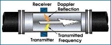
One Doppler meter design mounts both the transmitting and the receiving transducers in the same case, attached to one side of the pipe. Reflectors in the flowing liquid return the transmitter signals to the receiver, with a frequency shift proportional to the flow velocity, as is the case when the two transducers are mounted separately on opposite sides of the pipe.
A portable, clamp-on Doppler meter capable of operating on AC power or from a rechargeable power pack has recently been developed. A set of 4-20 mA DC output terminals permits the unit to be connected to a strip chart recorder or other remote device for readout and/or control.
|
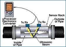
In the example shown in Figure 3, the sonic beam is at a 45° angle, with one transducer located upstream of the other. Each transducer alternately transmits and receives bursts of ultrasonic energy; the difference in the transit times in the upstream vs. the downstream directions (TU - TD) measured over the same path can be used to calculate the flow through the pipe:
| (5) |
where:
This equation shows that the liquid flow velocity is directly proportional to the meas-ured difference between upstream and downstream transit times. Because the cross-sectional area of the pipe is known, the product of that area and the flow velocity will provide a measure of volumetric flow. Such calculations are easily performed by the microprocessor-based converter. With this type of meter, particles or air bubbles in the flow stream are undesirable because their reflecting qualities interfere with the transmission and receipt of the applied ultrasonic pulses. The liquid, however, must be a reasonable conductor of sonic energy.
|
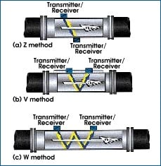
The Z configuration places the transducers on opposite sides of the pipe, one downstream of the other. Generally, the distance downstream is ~D/2, where D = pipe diameter. The converter uses specific data on piping parameters to compute the optimum distance. The Z method is recommended for use only in adverse conditions such as where space is limited, the fluid has high turbidity (e.g., sewage), there is a mortar lining, and when the pipe is old and a thick scale has built up on the inside wall that tends to weaken the received signals. It is not recommended for smaller pipes, where its measuring accuracy tends to degrade.
In most installations, the V method is recommended, with the two transducers on the same side of the pipe about a pipe diameter apart. The rail attachment that can be clamped on the pipe facilitates sliding the transducers horizontally along the pipe and positioning them the calculated distance apart.
The W method should be considered on pipe 1½ in. down to ½ in. dia. Its main limitation is a possible deterioration in accuracy due to buildup of scale or deposits on the pipe wall-note that the sonic signal must bounce off the wall three times. Turbidity of the liquid also could be harmful since the signal has a longer distance to travel.
Open-Channel Flowmetering. Ultrasonic flowmeters have been used successfully for certain open-channel flow measurements, in conjunction with weirs or flumes downstream. The transducer is installed above the channel, beaming pulses down on the surface of liquid in the channel. The pulses are reflected back to the transducer and the travel time can be related to the height of the liquid in the channel. Essentially, this is an application of an ultrasonic level detector. By relating the channel level with the flow velocity at the weir or flume, the metering system can provide a volumetric measure of flow.
Application Notes
It is essential to carefully follow the manufacturer's operating instructions. Early problems with ultrasonic flowmeters were perhaps due, at least in part, to the users' not understanding the importance of certain fundamentals such as proper mounting of the transducers on the pipe. The acoustic coupling to the pipe and the relative alignment of the transducers must be retained despite events such as a large change in pipe temperature or unusual vibration.
For both Doppler and transit-time flowmeters to indicate true volumetric flow rate, the pipe must always be full. A Doppler meter on a partially full pipe, however, will continue to indicate flow velocity as long as the transducers are both mounted below the liquid level in the pipe.
Most manufacturers specify the minimum distance that the meter must be from valves, tees, elbows, pumps, and the like, both upstream and downstream. This is usually expressed in pipe diameters and typically should be 10–20 diameters upstream and 5 diameters downstream.
Transit-time meters rely on an ultrasonic signal's completely traversing the pipe, so the path must be relatively free of solids and air or gas bubbles. Bubbles in particular tend to attenuate the acoustic signals, a problem that has been addressed in the Fuji Portaflow X shown in Figure 1. The unit's electronic circuitry uses a proprietary Fourier transform technique to provide what is termed an advanced antibubble measurement.
Doppler meters, on the other hand, rely on reflectors in the flowing liquid. To obtain reliable measurements, therefore, attention must be given to the lower limits for concentrations and sizes of solids or bubbles. The flow must also be rapid enough to keep these materials in suspension. One manufacturer gives as typical the values of 6 ft/s (1.8 m/s) for solids and 2.5 ft/s (0.75 m/s) for small bubbles.
Over the past few years, some suppliers of Doppler meters have introduced models that operate at frequencies >1 MHz. The claim for such units is that they will operate on virtually clean liquids because reflections will occur off the swirls and eddies of the flowing liquid. A cautionary note has been sounded, however, advising prospective users to limit the technique to low concentrations of bubbles and particles.
Because in the operation of ultrasonic flowmeters the energy for measurement passes through only part of the measured liquid, Reynolds number, which can be thought of as the ratio between the inertial forces and the viscous forces in a flowing stream, affects the performance of the meter. For example, to perform within their stated specifications, some Doppler meters and a type of transit-time meter require minimum Reynolds numbers of 4000 and 10,000, respectively. Here again, for such limitations the manufacturer's instruction should guide the user.
Clamp-on meters typically require that the thickness of the pipe wall be relatively small in relation to the distance the ultrasonic energy must pass through the measured liquid. As a general rule, the ratio of pipe diameter to wall thickness should be >10:1; i.e., a 10 in. pipe should not have a wall thickness >1 in.
When it comes to the stated accuracies of ultrasonic flowmeters there are still not a lot of independent test data to confirm or refute the claims made by various manufacturers. As the use of these meters becomes more widespread, one can hope that the availability of supporting data will equal that on orifice meters, supported by a wealth of test data and standards.
Both types of ultrasonic meters are finding new applications. One market research organization has determined that transit-time meter applications are increasing at a faster rate than are Dopplers. At present, the installations are split about 60/40 in favor of transit types. Developments in technology, however, can greatly affect this picture and only time will tell.
Also in Blog


Optimizing Cooling Tower Performance: Understanding Efficiency, Maintenance, and Water Quality Management