How does a cooling tower work ?

A cooling tower is a heat rejection device that rejects waste heat to the atmosphere through the cooling of a water stream to a lower temperature. Cooling towers may either use the evaporation of water to remove process heat and cool the working fluid to near the wet-bulb air temperature or, in the case of closed circuit dry cooling towers, rely solely on air to cool the working fluid to near the dry-bulb air temperature.
Common applications include cooling the circulating water used in oil refineries, petrochemical and other chemical plants, thermal power stations, nuclear power stations and HVAC systems for cooling buildings. The classification is based on the type of air induction into the tower: the main types of cooling towers are natural draft and induced draft cooling towers.
Cooling towers vary in size from small roof-top units to very large hyperboloid structures (as in the adjacent image) that can be up to 200 metres (660 ft) tall and 100 metres (330 ft) in diameter, or rectangular structures that can be over 40 metres (130 ft) tall and 80 metres (260 ft) long. The hyperboloid cooling towers are often associated with nuclear power plants,[1] although they are also used in some coal-fired plants and to some extent in some large chemical and other industrial plants. Although these large towers are very prominent, the vast majority of cooling towers are much smaller, including many units installed on or near buildings to discharge heat from air conditioning.
Once-through cooling was a common design feature for large power plants in the last century, as the process could effectively supply the high volumes of water needed for turbine exhaust steam condensation and auxiliary heat exchanger cooling. However, environmental concerns with regard to protection of aquatic creatures at both the intake and outfall of once-through systems have essentially eliminated once-through cooling for modern plants.
Now, cooling towers, or some variation thereof such as wet-surface air coolers (WSAC®) or even air-cooled condensers, are the norm. But this development comes at a time when many of the new combined cycle power plants, and other facilities for that matter, are being staffed by people new to the industry. Fundamental understanding is critical for proper operation of cooling water and other systems.
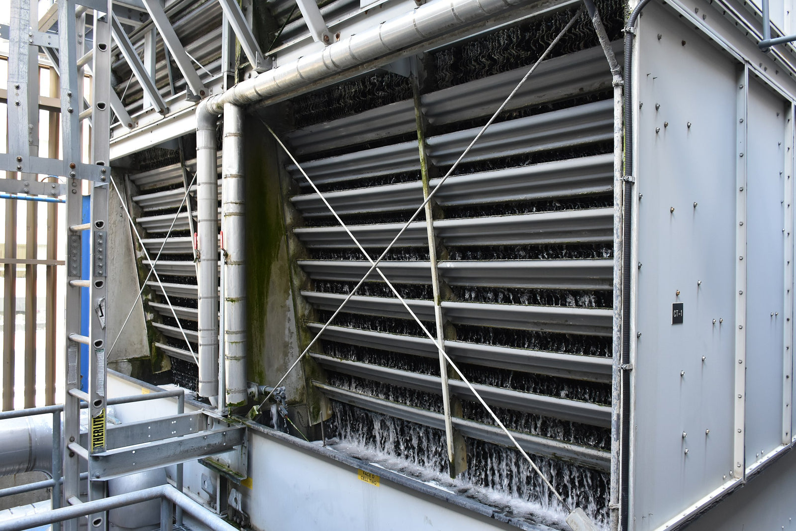
Cooling Tower Basics
For purposes of this discussion, we will focus on the most common industrial cooling tower, as illustrated below.

Figure 1. Schematic of one cell of an induced-draft, counter-flow cooling tower. Source: Post, R. and B. Buecker, “Power Plant Cooling Water Fundamentals”; pre-conference seminar to the 37th Annual Electric Utility Chemistry Workshop, June 6-8, 2017, Champaign, Illinois. To learn about future EUCWs, please go to the web site, www.conferences.illinois.edu/eucw
As the figure illustrates, warm effluent from the plant heat exchangers enters the tower and is sprayed over the cooling tower fill. Air enters the lower portion of the tower and contacts the water in a counter-current manner to help maximize heat transfer. The cooled water collects in a sump for return to the heat exchangers, while the warm air exhaust vents to the atmosphere.
A key component in cooling towers is the fill material, which further helps to maximize air/water contact. Shown below are two types, modern splash fill and the highest efficiency film fill.

Figure 2. Modern plastic splash fill. Photo courtesy of Brentwood Industries and Rich Aull of Richard Aull Cooling Tower Consulting, LLC.

Figure 3. High efficiency cross-flute film fill. Photo courtesy of Brentwood Industries and Rich Aull of Richard Aull Cooling Tower Consulting, LLC.
A number of intermediate choices are available, where the selection is dependent upon the projected cooling water quality and the potential for fouling in the media, which the author will address in a future article for Power Engineering.
The next section examines the fundamentals of heat transfer in a cooling tower.
Some Basic Heat Transfer Calculations
Figure 4 illustrates actual conditions that might be seen in a cooling tower operating on a mild spring day.

Figure 4. Example of a real-world set of conditions for a cooling tower. Source: Potter, M.C. and C.W. Somerton, Schaum’s Outlines Thermodynamics for Engineers; McGraw-Hill, New York, NY, 1993.
Notice that the relative humidity (RH) of the inlet air is 50 percent, while the RH of tower exhaust is nearly 100 percent. This data helps to illustrate that the primary method of heat transfer in a cooling tower is via evaporation of what is typically a small fraction (2 to 3 percent) of the recirculating water. While the mathematics of cooling tower flow design can be somewhat complex, several simple equations have been developed to straightforwardly approximate the evaporation, blowdown, and makeup flows to a cooling tower.
The standard formula for evaporation is,
E = (f * R * DDT)/1000, where Eq. 1
E = Evaporation in gpm
R = Recirculation rate in gpm
DT = Temperature difference (range) between the warm and cooled circulating water (oF)
¦ = A correction factor that helps to account for sensible heat transfer, where ¦ typically ranges between 0.65 to 0.90, and which rises in summer and declines in winter
The factor of 1,000 is a good approximation of the latent heat of vaporization (Btu/lb) of water at ambient conditions. From some previous work done by the author, ¦ for the example in Figure 2 calculates to 0.78. So, the evaporation rate for this example, with a recirculation flow of 150,000 gpm and a range of 27o F, is 3,159 gpm.

A very important concept for understanding cooling tower heat transfer is that of “wet bulb” temperature, which is the lowest temperature that can be achieved by evaporative cooling. Unless the relative humidity is 100 percent, the wet bulb temperature will always be below the ambient or “dry bulb” temperature. Thus, cooling towers can virtually always cool the circulating water to a lower temperature than ACCs. In the example from Figure 2, the wet bulb temperature at inlet air of 68oF, and 50 percent RH is near 57oF, so the approach to wet bulb for that example is 77o – 57o = 20o F. With modern, well-designed cooling towers, lower approach temperatures are quite possible.
Cycles of Concentration and Water Quality Impacts
Evaporation causes dissolved and suspended solids in the cooling water to increase in concentration. This concentration factor is (logically) termed the cycles of concentration (C, or COC). C, or perhaps more accurately, allowable C, varies from tower to tower depending upon several factors including makeup (MU) water chemistry, effectiveness of chemical treatment programs, and potential restrictions on makeup or discharge quantities. The algebraic equation for calculating the cycles of concentration is:
C = MU/BD Eq. 2
Comparison of the concentrations of a common ion such as chloride or magnesium in the makeup and recirculating water will determine cycles of concentration, but common in the field to calculate C is on-line measurement of the blowdown (BD) and makeup (MU) specific conductivities. The measurements allow for instantaneous blowdown adjustment to maintain the desired C value. In all cases, the cycles of concentration has a cutoff point, where further increases can lead to scaling or corrosion issues in the cooling system, even with good chemical treatment.
The ratio of blowdown to evaporation is outlined by the following equation:
BD = E/(C – 1) Eq. 3
Besides blowdown, some water also escapes the process as fine moisture droplets in the cooling tower fan exhaust. This water loss is known as drift (D). Modern mist eliminators can reduce drift to 0.0005% of the recirculation rate, and Brentwood Industries has come out with a design that reaches 0.00025% drift rate. Leaks in the cooling system are referred to as losses (L). The following equation show the relationship between makeup and evaporation, blowdown, drift, and any other losses.
MU = E + BD + D + L Eq. 4
With a well-designed and operated tower, the last two terms are negligible, so the water requirements of the tower are basically functions of evaporation and blowdown. Returning to equation 3, the figure below illustrates the relationship in blowdown rate vs. cycles of concentration for the tower illustrated in Figure 2.

Figure 5. Blowdown vs. cycles of concentration.

As is clearly evident, the curve is asymptotic, and the reduction in blowdown at higher cycles drops off dramatically with increasing C. The author has seen more than one set of specifications where the design engineers have selected a high cycles of concentration, seemingly without regard to the minimal benefits in water savings derived thereby. What does occur is greatly increased challenges regarding water treatment chemistry due to the high concentration of scale- and corrosion-inducing impurities.
Also in Blog


Optimizing Cooling Tower Performance: Understanding Efficiency, Maintenance, and Water Quality Management