Boiler Blowdown Automation Basics

Blowdown Basics
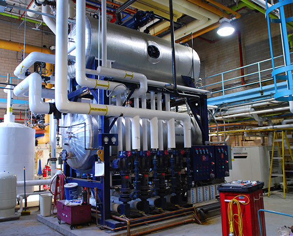
- Boilers generate steam used for heating or manufacturing processes.
- When steam leaves the boiler, impurities (TDS – total dissolved solids) are left behind to accumulate in the boiler.
- Accumulation of TDS beyond their solubility limit results in the formation of scale. D. Blowdown is the process of removing water with high concentrations of TDS and
replacing it with fresh makeup water with lower levels of TDS, thereby lowering the overall TDS in the boiler.
- Two types of blowdown: Bottom blowdown – removes sediment/sludge from the bottom of the boiler; Surface skimmer blowdown – removes high‐TDS water near the surface (6” below the water line). Automated controllers only regulate surface blowdown (illegal to automate bottom blowdown).
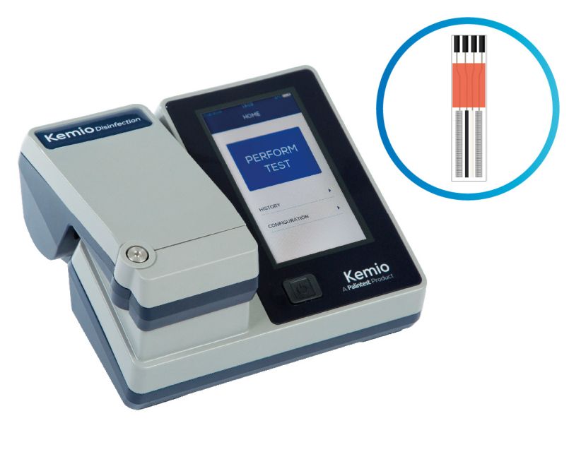
- TDS can be directly measured by lab tests (costly, time consuming) or can be approximated by conductivity measurements (inexpensive, quick, accurate).
- Two types of surface blowdown: manual and automated
Manual Blowdown
- Involves manually opening a blowdown valve at various times throughout the day; used in conjunction with a hand‐held conductivity meter to keep some degree of control over TDS levels.
- Results in high and low conductivity spikes due to boiler load variances.
- Conductivity levels above the target maximum lead to the formation of scale. Conductivity levels below the target maximum result in excess water and chemical usage.
- At best, manual systems err on the safe side and keep TDS too low. E. Excess water usage has several costs:
- City water costs 2. City sewer costs
- Energy costs (heated water is sent to drain) 4. Chemical costs (tied to water usage)
- High TDS = Scale Formation = Energy Inefficiencies
- 1/16” layer of scale results in a 10% minimum reduction in heat transfer efficiency (a percentage reduction in heat transfer efficiency = a direct percentage increase in heating costs).
- Extreme scale build‐up leads to costly de‐scaling procedures or the replacement of boiler tubes or complete systems.
Automated Blowdown
- Uses an automated controller and valves to continuously or intermittently sample the boiler water and then blowdown as needed.
- Types of Automated Blowdown
- Continuous Sampling – Used when steam blowdown requirements exceed 5000 lbs./hr. (see selection guide). A sample of water is continuously sent across the conductivity probe to drain. When conductivity levels exceed the target maximum, a larger blowdown valve opens and sends more water to drain until the set point is satisfied.
- Timed Sampling (most common) – Used when steam blowdown requirements are less than 5000 lbs./hr. A sample of water is intermittently sent across the probe for a predetermined amount of time (interval and duration are adjustable), and the blowdown valve is held open until the conductivity set point is satisfied.
- Cost Justification
- Auto blowdown allows for much tighter control of conductivity levels (typical 20% increase in conductivity levels vs. manual control; this equals a direct 20% savings in fuel)
- Less blowdown and makeup required = lower water and sewage bills c. Less water usage = lower chemical costs
- Less testing and manual care required (time freed up for more productive work)
- Prevention of scale formation – protection of capital equipment costs
- Average payback for a typical system is a couple of months (see “Cost Justification” sheet).

Typical Installation (See timed‐sampling drawing)
A. Required components
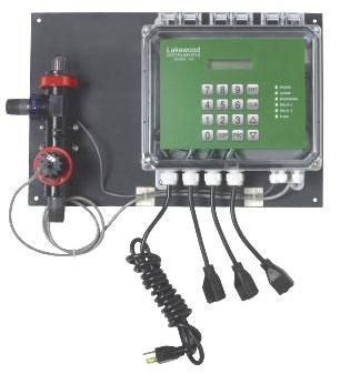
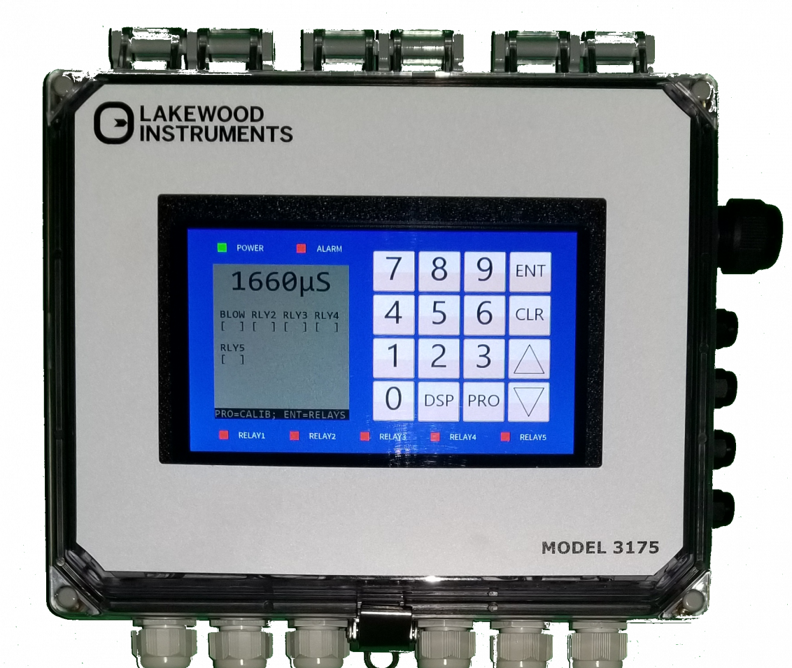
- Blowdown controller (analog or microprocessor‐based)
- Throttling valve (gate, globe, needle, orifice plates)
- Blowdown valve (solenoid valve, motorized ball valve
- Probe should be located as close to the boiler as possible in a 1” fully ported line (close proximity minimizes the length of time required to heat the probe and obtain an accurate reading).
- Throttling valve should be located 6”‐3’ downstream of the probe to prevent steam flashing. Steam flashing will shorten probe life and cause relay chattering.
- Separate low voltage conductivity wires from other high voltage wires to prevent erratic readings.

Installation Notes:
Conductivity probe and mounting cross should be installed as close to the skimmer port as possible in a 1” fully ported line with no bends or restrictions. An isolation valve should be installed upstream of the conductivity probe for ease of probe removal and maintenance.
2) A flush valve (1/4 turn ball valve) should be installed on the bottom leg of the 1” mounting cross for sediment removal and probe cleaning.
3) The throttling valve should be installed between 6” and 3’ downstream of the conductivity probe to prevent steam flashing across the probe.
4) The blowdown valve should be located far enough downstream of the throttling valve to distance it from high temperature areas. Many blowdown valves feature thermal cutoff switches that can be triggered by high ambient temperatures.
Automated Blowdown Cost Justification
hat is the most common “objection” to the purchase of an automatic boiler blowdown system?
Right, it costs too much! Here’s a suggestion to help overcome that objection. Analyze the operation and come up with the payback figure.
Take the following example:
A process boiler producing 100,000 pounds per hour of steam: The operator has been told to maintain chlorides at 18‐22 ppm. His records show that he averages 20 ppm, which is pretty good for manual blowdown.
However, automatic blowdown could bring the average up to 21 ppm without exceeding 22. This would reduce the blowdown by 5% (21‐20) / 20 = .05 or 5%
Typically, 20 ppm results from 10 cycles of concentration. The blowdown required to maintain 10 cycles is 10,000 lbs/hr (100,000 / 10 = 10,000)
If the 10,000 lbs/hr is reduced by 5%, that’s a savings of 500 lbs/hr. 500 lbs/hr at 400 BTU/lb is 200,000 BTU/hr. A gallon of oil is about 100,000 BTU, so the oil consumption will reduce by 2 gal/hr. At a dollar a gallon, that’s a $2 savings every hour!
If an automatic blowdown system costs $1300, it will take 650 hours (or 27 days) to pay for the system!!! ($1300 / $2 per hr = 650 hours); (650 hours / 24 = 27 days)
This was all based on zero condensate return. If there is 50% return, the payback period doubles in 54 days. That’s still a very short payback period. Of course, the savings continue after the payback period.
Also in Blog


Optimizing Cooling Tower Performance: Understanding Efficiency, Maintenance, and Water Quality Management